Tuesday, April 26, 2016

1st order op amps

Today we began with a short derivation of an integrator op amp.

These are the graphs to the integrator.

We then moved on to a short experiment and solved for a resistor that did not saturate the op amp.  That resistor was a 1kohm and the frequency was at 1kHz with a .5V source.
Below is a picture of the circuit.


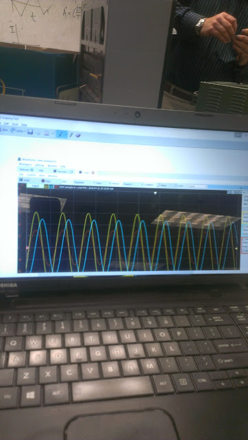
The graph at 1kohm, 500 Hz, .5V.

Below is a graph with 2kHz, 250mV and our resistor at 680.hm.
Here we learned about the unit step function and the graphs to the derivation.                                                                                                                                                                                                                                            


We then worked on some examples to solve for v(0), v(infinity), and tau.

Below is an exercise solving for the current where the inductor is treated like a wire.


Thursday, April 14, 2016

week 8 1st order circuits.

We began the day with a guess to what a capacitor circuit looks like as it discharges.


Here is a derivation of 5 time constants to get to 1%.


 Here we derived power and energy equation for first order circuit.
 Here we found the voltage and current with v(0)=10 and tau = 5 time constants.

We then found the frequency to a period of this time signal.

Then we found the time for this RC Circuit.


In this experiment we observed the behavior of a time signal when we removed a wire and reattached it manually.  We also did this with the analog discovery using waveforms.


A schematic of the circuit implemented shown below.


A Picture of the experiment using the waveforms program without manually removing the wire.

Our results for the inductor lab.


Tuesday, April 12, 2016

Week 8 Capacitors

Today we learned about capacitors.  Here we learned about variable capacitors where capacitance is determined by the distance of the aluminum plates.


 Our thoughts on how to construct a variable capacitor.

 Here we used source transformation to solve for voltage across the 4k and 2k resistors.  Then we solved for energy across the capacitance.

Checking our work by the professors solution.


The graphs for the sinosoidal and triangular waves for our experiment.

 The circuit for the experiment.

We ended the day with a lecture on inductance.


Thursday, April 7, 2016

Week 7 OP Amps 3

Today we started with an exercise to find Vo of the circuit.

Identifying the two non inverting op amps and solving for Vo.


The professor's solution confirmed our solution.


In the wheatstone bridge experiment we obtained gain after constructing the circuit and powering the op amp.  


A video of our wheatstone bridge experiment.


The diagram of the completed circuit.


Tuesday, April 5, 2016

Week 7 day 11

Today's exercise Gain= -Rf/Ri we get -3v. Since the op amp goes from 0v-9v our square wave gets chopped off to zero with an amplitude of 300mv.


Another exercise using nodal analysis  where vb=vs=0.

A calculation of a non inverting op amp V0=(1+Rf/Ri)Vi.


For Summing amplifier V0=-Rf(V1/R1 + V2/R2+ V3/R3).

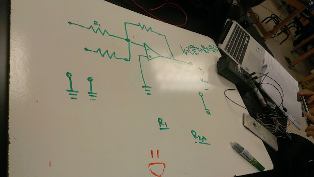
The circuit for the summing inverter which increased voltage and did not saturate after our second trial.  We started with R1=1.8Kohms and R2=3.6 Kohms.  We switched the values to achieve non saturation.
The graph of our two circuits blue is the circuit that did saturate and red is the one that did not saturate.

In this exercise we found R2 and R4 to be 20k in order to get a gain of 2.

Difference
V0=R2/R1(V2-V1)

Just as we predicted.