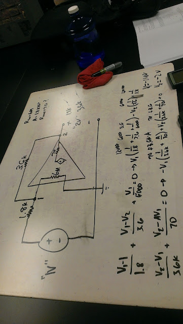
Today we began learning about Op Amps. We learned what an open circuit and a closed circuit is. Open circuit doesn't give feedback and closed does.
In this example we redrew a circuit with an op amp in terms of a voltage source and resistors in series. Then we used node voltage to find v1 which is Vd and v2. Then we used the ratio vout/vin=gain to find the voltage gain.
Another example of finding gain.
We designed a circuit with a gain of 2 volts. Using the schematic for the OP 27 we found the output resistance for the open loop to be 70 ohms. We found the input voltage to be -1.1v and output voltage to be -2v.
We then tested the circuit with the analog discovery ranging from -3v to 4v to plot the inverse.
Tuesday, March 29, 2016
Tuesday, March 22, 2016
Week 5 day 9
Here we solved for the power of the circuit.
On this circuit we solved for the power at different resistor values.
On this circuit we found the resistance of each battery in the circuit and found their equivalent resistance inverted and set that equal to Rth. Rth is.028 ohms and Vth is 24v. The power is 5052W(180)=909kJ we found the current to be 10.5 amp hours.
We graphed the power vs the resistance of a potentiometer in a circuit..
The table is shown below.
A zoomed version of the graph.
Our work done on the board for the graph.
Our results matched that of the professor.
Our work done for the exercise on this circuit solving for Rth and the voltage going out.
Week 4 day 8
Today we learned how to find R Thevenin and V Thevenin. By using circuit analysis in this case superposition and source transformations we easily found Vth and Rth.

An exercise on source transformations to find the current i0.
Here we short the voltage an set the current to open to find Rth and use source transformation to find Vth.
Another excercise where we solved for Vth and Rth.
An excercise using mesh current analysis to find the current and then we found Vth and solved for Rth.
A picture on how the potentiometer works and the graph we should get from our experiment.
Here we tested the values of the potentiometer to get the voltage from each value of the resistance inside it.
Here is the graph of the table P vs R
Week 4 day 7
Here we used the analog discovery to display the frequency on waveforms.
Here we got a nice sine graph.
Here the frequency increased as seen on the sinusoidal wave.
A triangular wave shown below.
Finally the square wave.
Our sketch of the graphs above.In this experiment we solved for R equivalent to find our total voltage. We got V=1.38
With both voltages on we get a total of 2.67 volts.
We tested the voltage on the circuit below.
Week 3 day 6 superposition
We started off by learning superposition by removing the current source to make a big mesh.
We used the mesh current analysis to solve for the three currents in each mesh.
Then we tested the circuit to see if our results were correct, but found we made a mistake in our calculations.
We ended the day by solving the voltage source of a circuit.
Tuesday, March 8, 2016
Week 2 Day 3
We began the day by testing whether the leds would light up connected to the hot dog weiner. It turns out they do when horizontal, but not vertical.
Attached is a video of this experiment.
This is our prediction of what we thought would happen. That being a will be brighter, b less brighter, and c very dull.
Then we moved on to another exercise to solve for i0 using KCL.
In this exercise we solved for Vout using KVL and we got 870 ohms.
Then we moved on to another exercise to solve for power used in the system.
Week 3 Day 5 Nodal Analysis
We began the day with an exercise on super nodes. Using nodal analysis we were able to identify our currents and solved for our unknown voltages.
The professor corrected our results and we realized we made errors where the voltages would be at their max in our equations. That is we wrote our voltages in our equations reversed.
The we began the experiment on Nodal analysis. We solved for V1 and V2 to get 4.39v for V2 and 2.39 for V1. Below is the implemented circuit with our 3 power sources.


It turns out the resistor have a 10% uncertainty. So we calculated the two voltages based on the uncertainty. Then we tested the circuit with the voltmeter.
After trying to figure out why our V1 was coming out with the wrong values we figured it was probably touching another resistor or something else. So we carefully removed the resistor and reconnected it to find our V1. Our percent error was 0.67% for V2 and 2% for V1.
Subscribe to:
Comments (Atom)


